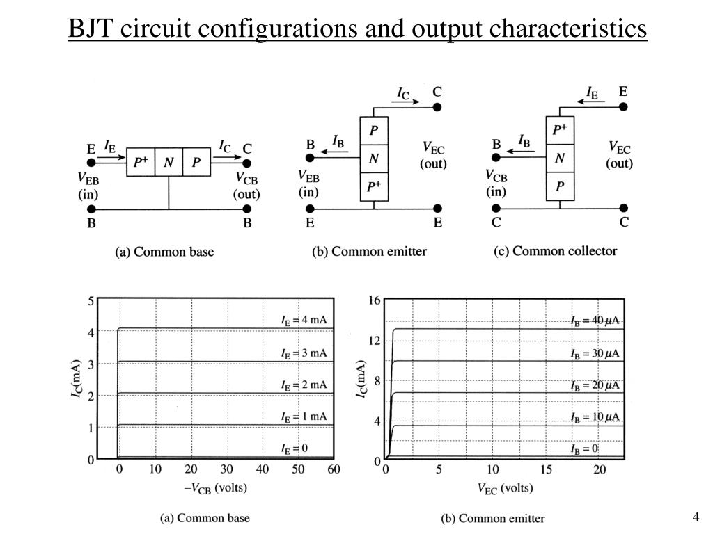
Generally speaking, higher gain means more amplification potential but can also lead to more noise and distortion in the signal chain.Ģ. This parameter is closely related to the device’s input and output impedances and can be calculated using the formula hfe=Vout/Vin. Gain: The gain of a BJT amplifier is determined by its current gain, also known as its beta value. Here is a breakdown of five of the key parameters that define a BJT amplifier:ġ. As such, it is important for engineers to understand the basic parameters of these amplifiers and how they affect performance. They are used in applications as varied as amplification, switching, and signal processing. What are the five important parameters of a BJT amplifierīipolar Junction Transistor (BJT) amplifiers are some of the most widely used components in electronic circuits. It can also be determined experimentally using an oscilloscope probe but this method is time-consuming and difficult to set up. In conclusion, calculating the voltage gain of a BJT requires knowledge of electrical concepts such as Ohm’s Law, Kirchhoff’s Voltage Law and transistor biasing equations. This method gives an accurate result but can be time-consuming and difficult to set up. The readings are then plotted on a graph against frequency, which will show how the voltage gain changes with frequency.


This is done by connecting an oscilloscope probe to both input and output terminals and taking readings for different frequencies. The voltage gain of a BJT can also be determined experimentally. The voltage gain is then calculated by dividing VCEQ by IcEQ. The operating point is found by calculating the quiescent values of collector-emitter voltage (VCEQ) and collector-emitter current (IcEQ). These equations are used to determine the operating point of a transistor, which is necessary for calculating its voltage gain. The voltage gain of a BJT can also be calculated using transistor biasing equations. This is done by taking the ratio of the base current to the collector current and then multiplying it by the ratio of the collector current to the emitter current. Once these values are known, you can calculate the voltage gain by dividing the output voltage by the input voltage. These values can be found using Ohm’s Law or Kirchhoff’s Voltage Law. To calculate the voltage gain of a BJT, you need to first identify the base, collector and emitter currents. The voltage gain of a BJT is determined by the relationship between the base current, collector current and emitter current. A BJT circuit consists of a number of components including a base, collector and emitter. It is defined as the ratio of the output voltage to the input voltage and can be calculated using Ohm’s Law, Kirchhoff’s Voltage Law and other related equations. Voltage gain is an important parameter in determining the overall performance of a bipolar junction transistor (BJT) circuit.

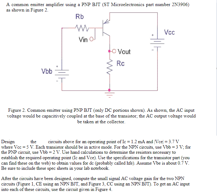
What are the five important parameters of a BJT amplifier.This is the way that the circuit would usually be shown. Because it is normal to show the supply voltage with the positive terminal uppermost, the circuit of Fig. 5-16(a) note that the voltage polarities and current directions are reversed compared to npn transistor base bias circuits. Figure 5-16 shows circuits that use pnp transistors.

Base Bias Using pnp Transistor:Īll of the Base Bias in BJT circuits discussed so far use npn transistors. In circuit analysis it is sometimes convenient to use a typical h FE value. The transistor is usually identified by its type number, and then the maximum and minimum values of current gain can be obtained from the manufacturer’s data sheet. However, In practice the precise current gain of each transistor is normally not known. When the transistor dc current gain is known, it is quite easy to determine the circuit bias conditions. Thus, when the supply voltage and component values are known, a Base Bias in BJT is easily analysed to determine the circuit current and voltage levels. 5-1 (V CE = V CC – I CR C) to calculate the collector-emitter voltage. The collector current is now used with Eq.


 0 kommentar(er)
